|
How to make a re-radiating antenna for the Garmin Etrex family, using the GA27 active antenna,
Motivation: Before I upgraded to the Etrex Vista I used the GPS12XL for some years. And while the GPS reception in my car is very bad with the receiver mounted in an easy-to-read position, I used the GA27 antenna put on the dashboard. Now, the Etrex family does not come with a connection for external antenna. There are some re-radiating antennas on the market but I found a way to save this money, using the old GA27. Please note that this is not an instruction to make a receiving antenna. I made e repeater system and I used a commercial receiving antenna with amplifier. The basic idea: The basic idea was not mine. I read a paper written by Dave Martindale. He made a re-radiating antenna for his GPS38, long before the Etrex family came out. I found his instructions very clear and, in the end, correct. You find it here and you should read it in order to understand what I did. There is only one point that I did not find working: he recommended a GPS45 helix antenna to be used as the transmitting antenna but this did not work well with my Vista. The final arrangement is shown in the following diagram. I made the transmitting antenna, and the adaptor box. Within this box, power supply for the Etrex and for the GA27 is generated out of the car supply (12 to 14 Volts), and the antenna signal is coupled to the transmitting antenna.
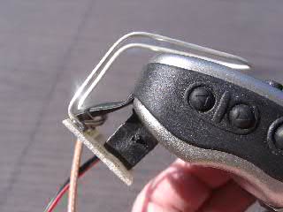
The transmitting antenna: It was very easy to make the transmitting antenna out of a silver plated copper wire. I found that it is essential to keep the whole wire length at approximately 190 mm (one wavelength), but it is not required to have the full length on top of the Etrex body. So I found a way to fix the loop on a small printed board, and this board is fixed by a screw and some glue on the Pfranc connector for power supply, see the photos below. I just connect the power supply and the antenna is in place. Works very well. The reception is stronger than with the pure Etrex.
The wiring Dave Martindale gave instructions on how to do the power supply of the GS27 and the wiring. I did all as he said, but I use only one MCX connector on the supply box. The wire leading to the antenna loop is soldered directly to the coupling capacitor inside the box. I don't need the additional BNC connector, and this way it was easier to keep all connections in a good 50 Ohms shape. The Adaptor Box For the power supply of both the Etrex and the GA27 I use only one current loop, see the diagram below.
The upper part of the diagram is the supply for the Etrex. I use a variable linear regulator LM117 to create the 3 volts needed. The capacitors in the diagram are not given as values. They are bypass or coupling capacitors and everyone will prefer other values. In general a linear regulator is not a good solution here because most of the 12 volts from car supply is wasted, so a switching regulator is generally said to be better. But note the 5.1 Volts Zener diode in the supply line. Whenever the Etrex is on, its 50 to 200 mA current will keep the Zener diode alive, and it can act as another 5 Volts supply for the lower branch in the diagram, supplying the antenna current of max. 15 mA. In fact the antenna supply is not referring to the same ground as the car and the Etrex, but this does not matter at all because there is no galvanic connection between the antennas and the Etrex. As a side effect, the antenna supply is cut automatically whenever the Etrex is off. No extra switch is needed for the antenna. Any more questions? You'll find me here. |